R0036 Rev A.1 Active
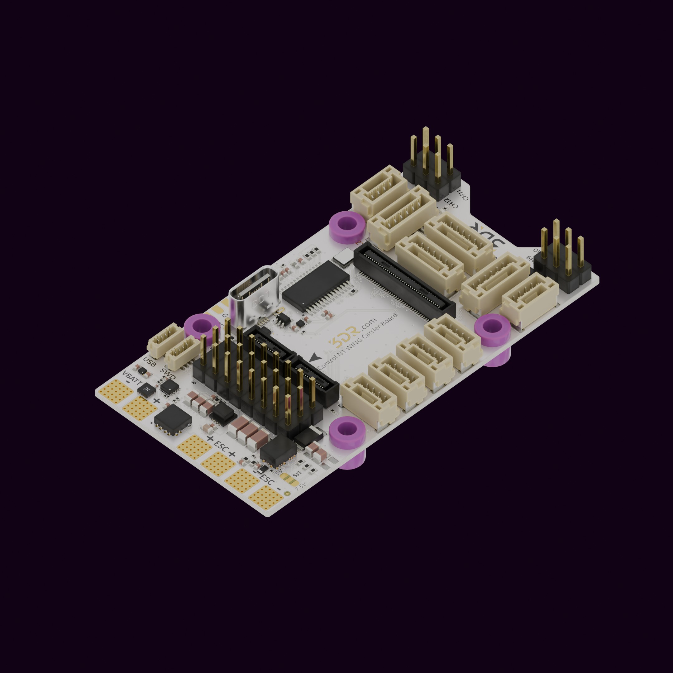
Engineered to go the distance. The R0036 is a carrier board for the Control N1 built for fixed-wing UAV platforms, handling ESC power distribution for up to two props with an onboard OSD for analog video flight data.
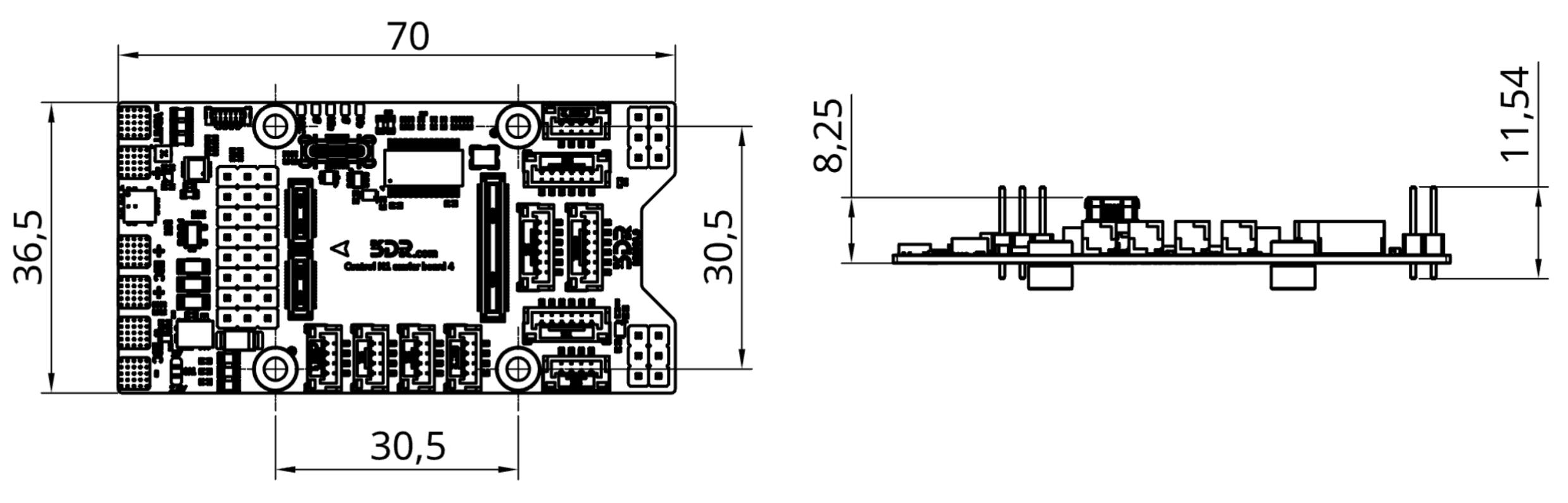
Specifications 3DR N1 Carrier 4 - Wing (R0036) Mounting Holes M3, 30.5 mm x 30.5 mm Weight TBD Dimensions See Mechanical Information
Electrical Specifications 3DR N1 Carrier 4 - Wing (R0036) Operating voltage 6.4V – 28V max (6S LiPo) Peripheral output voltage 5V at 600mA Servo voltage 5V or 7.5V, selectable via SJ1
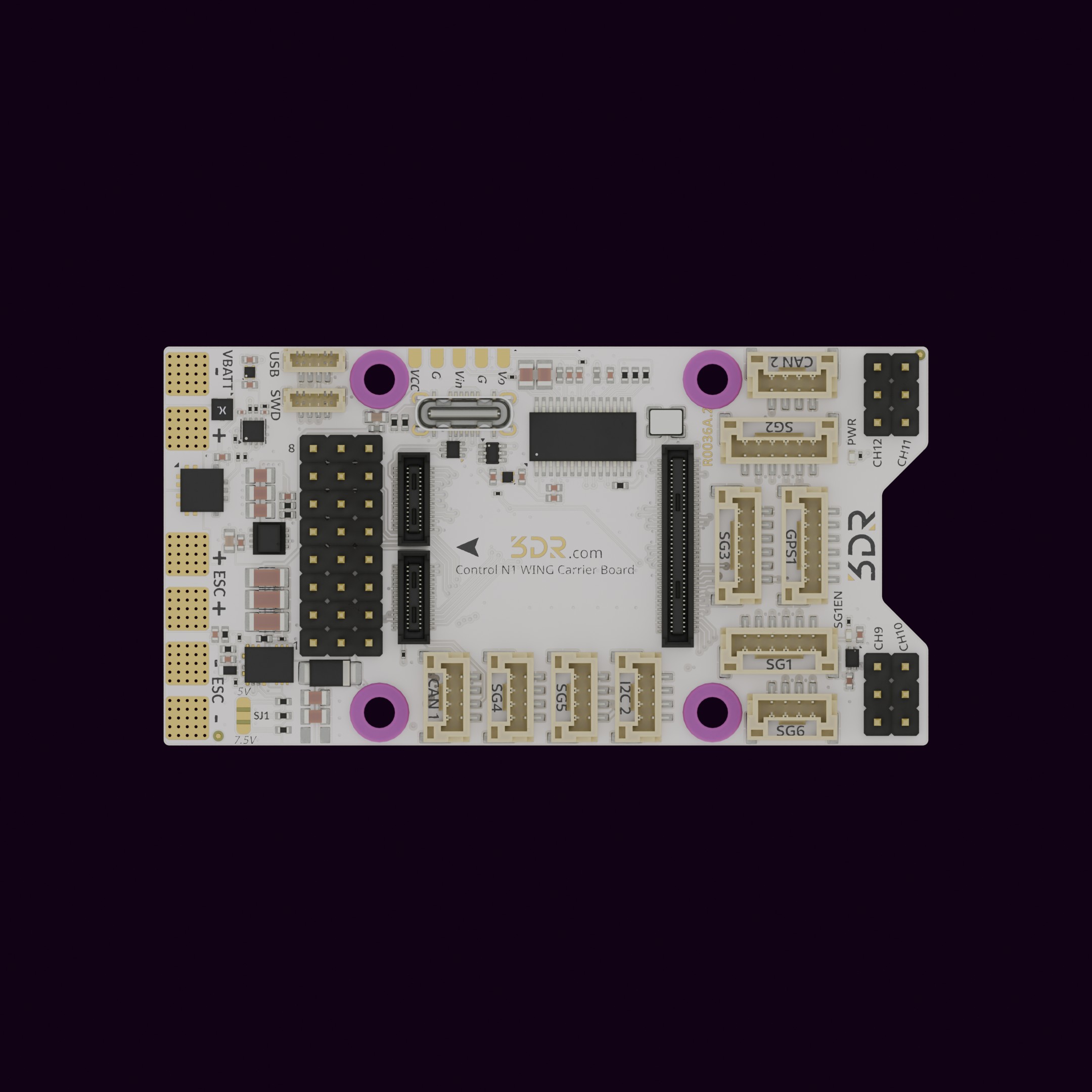
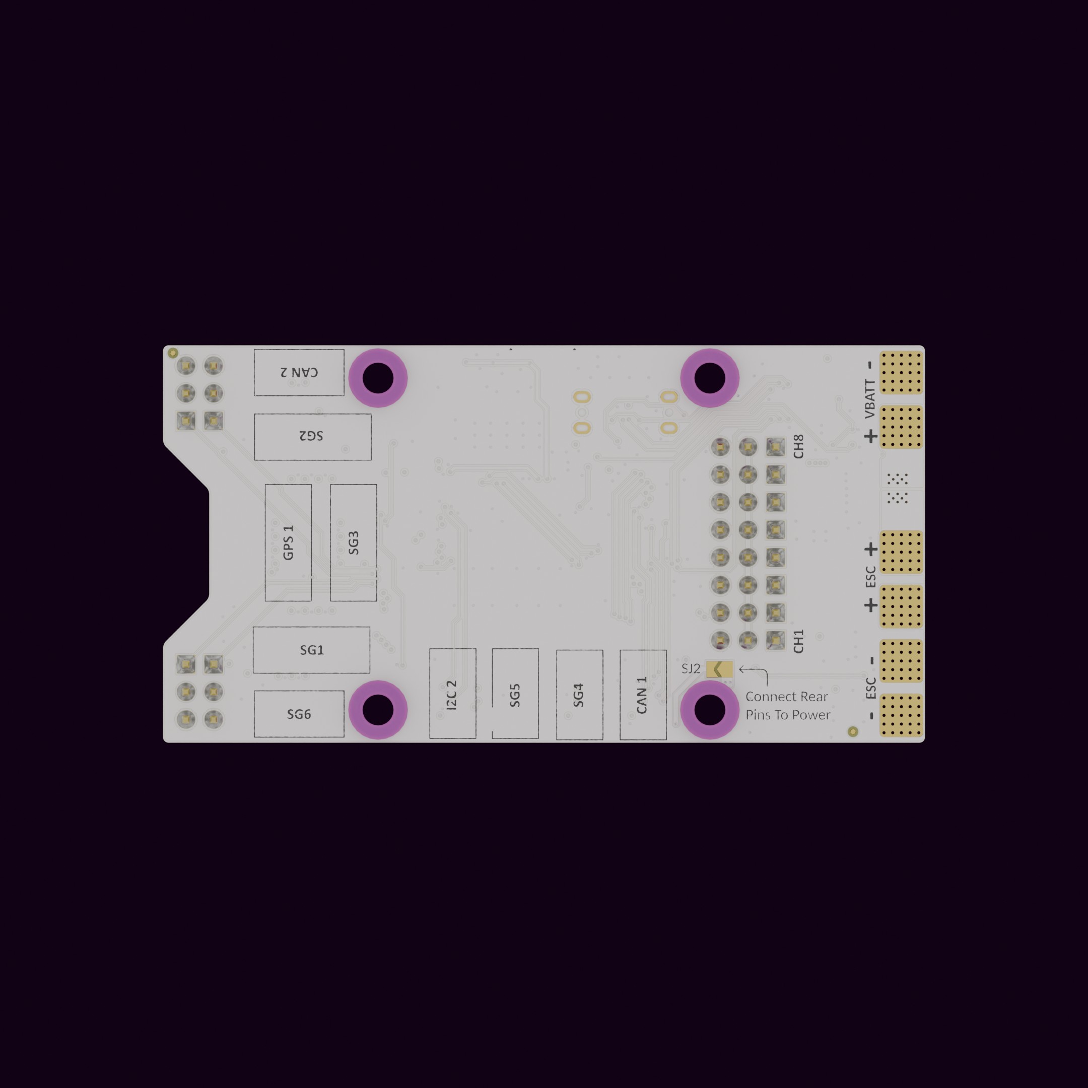
Port Connection Type USB-C USB-C USB (JST SUR) JST SUR VBATT Pads ESC 1 Pads ESC 2 Pads PWM (1–12) Pin Headers OSD Pads SG1 w/Flow Control Connector SG2 w/Flow Control Connector SG3 w/Flow Control Connector SG4 Connector SG5 Connector SG6 Connector GPS1 Connector I2C2 Connector CAN1 Connector CAN2 Connector
Unpack the product and inspect for any visible damage. Align the connector/interface with the corresponding port on Control N1 (R0024) . Secure the connection by pressing firm and equally both boards against each other. Power On the base product to verify successful integration. Pad Signal Description 1–12 CH1–CH12 PWM signal outputs GND GND Ground (shared)
Pad Signal Description 1 VCC Power supply 2 GND Ground 3 Vin Video input 4 GND Ground 5 Vout Video output
Pin Signal Description 1 5V 5V power output 2 S7_TX Serial transmit 3 S7_RX Serial receive 4 I2C_SCL I2C clock line 5 I2C_SDA I2C data line 6 GND Ground
Pin Signal Description 1 +5V +5V power output 2 S(1,2,3)_TX Serial transmit (UART TX) 3 S(1,2,3)_RX Serial receive (UART RX) 4 S(1,2,3)_CTS Clear To Send (hardware flow control) 5 S(1,2,3)_RTS Request To Send (hardware flow control) 6 GND Ground
Pin Signal Description 1 +5V +5V power output 2 S(4,5,6)_TX Serial transmit 3 S(4,5,6)_RX Serial receive 4 GND Ground
Pin Signal Description 1 +5V +5V power output 2 SCL I2C clock line 3 SDA I2C data line 4 GND Ground
Pin Signal Description 1 +5V +5V power output 2 CAN_H CAN bus high 3 CAN_L CAN bus low 4 GND Ground
All pads are labeled on the board itself.
VCC Pads ESC 1 ESC 2 Power Module (5V, 600mA) SJ1 PWM CH1-8 SJ2 PWM CH9-12 GPS1 SG1–SG6 I2C2 CAN1 / CAN2 OSD Clean with a dry cloth; avoid moisture or abrasive materials. Periodically check connection points for wear or loosening. Store in a cool, dry place when not in use. If you have further questions, contact us .