

Control N1
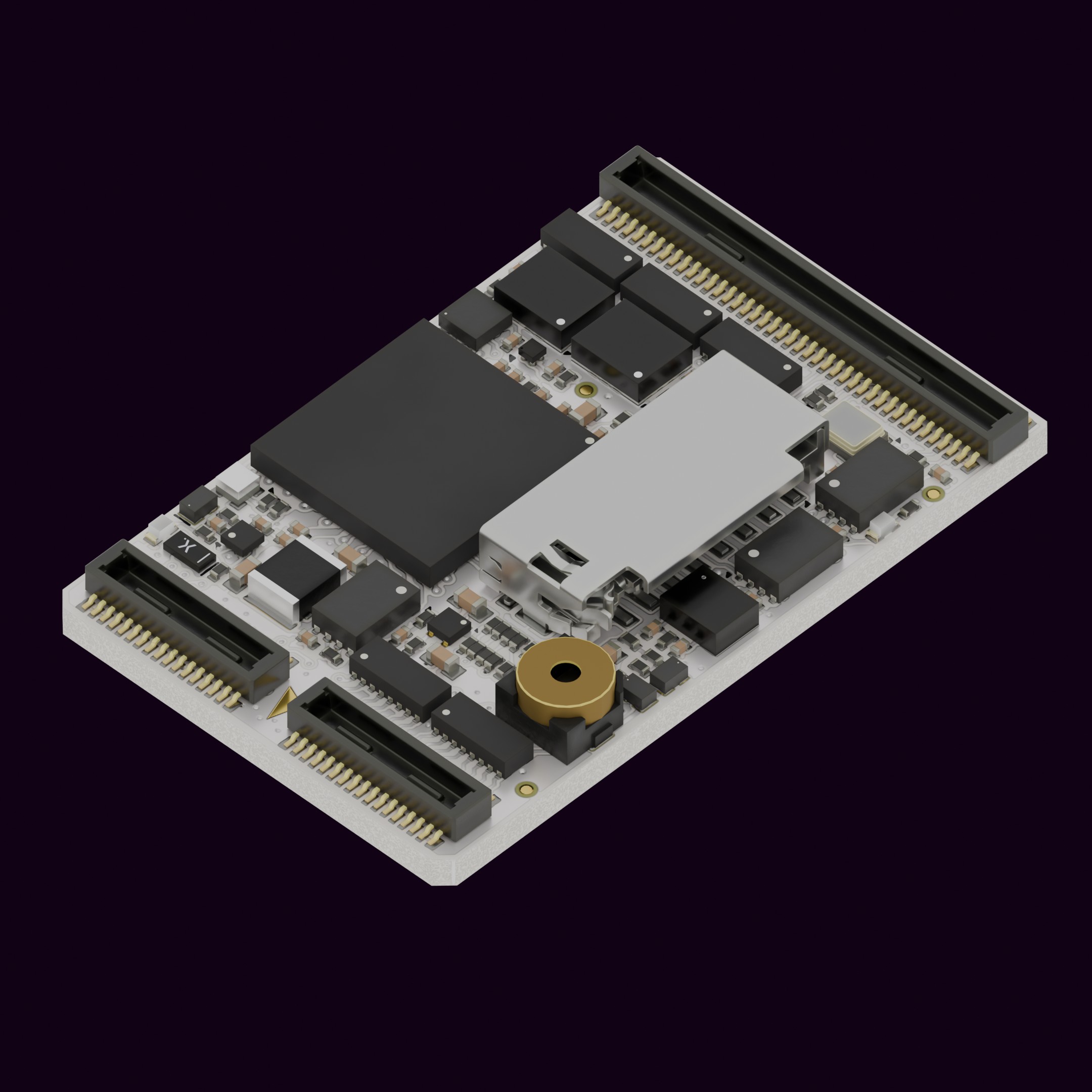
Meet Control N1. Our smallest, lightest, and most versatile AutoPilot Module. At just 17.6mm × 28mm and 2.3g, this tiny powerhouse brings full ArduPilot and PX4 flight control to even the most space and weight constrained designs yet remains a cost effective solution.
Key Features
Section titled “Key Features”- Ultra-Compact & Feather-Light - Barely bigger than a stamp — 17.6×28mm and under 2.7g -, the N1 integrates into small UAVs, ROVs, UUVs, and custom robotics platforms without compromise. Forget about frame resonances hitting the same resonant frequency as your autopilot.
- Based on the industry standard Cortex-M7 architecture H7 MCU.
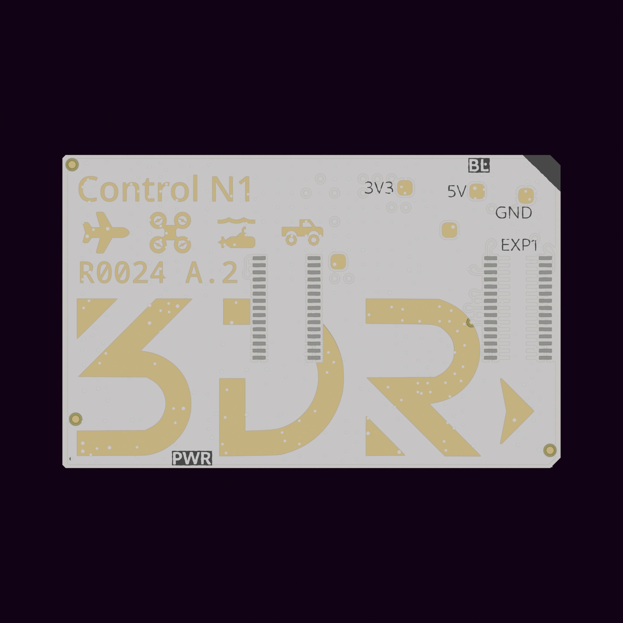
- Single-Sided design - We’ve engineered the entire autopilot onto a single sided PCB, minimizing board area and assembly complexity.
- Flexible and Future-Proof board to board interface - Designed with the future in mind, our board footprint –with a connector type similar to a Raspberry Pi compute module–, exposes extra pins so you can reuse all your existing carrier/main boards whenever new hardware is available.
- Best in class sensor selection - We didn’t pick components on paper alone. Extensive testing and experience determine our picks. Expect performance ahead of the curve, especially with the thermal compensation option.
- Affordable, US Made Excellence - Proudly designed and manufactured in the USA, the N1 undercuts bulkier, heavier and more expensive competitors while delivering premium flight control features. We don’t cut corners where people can’t see, we only use Tier 1 component brands.
- Open source ecosystem - As our core tradition, we offer full compatibility with ArduPilot and PX4 communities means instant access to mature firmware, mission-planning tools, and global support.
Order now!
3D View
Section titled “3D View”Specifications
Section titled “Specifications”General
Section titled “General”| Autopilot | Control N1 |
|---|---|
| Main processor | STMicro® STM32H743 Arm® Cortex®-M7 core, double-precision FPU up to 480 MHz fCPU |
| L1 cache | 16 Kbytes of I-cache 16 Kbytes of D-cache |
| RAM | 1 MB |
| Flash | 2 MB |
| Memory | 8 MB (Page EEPROM) |
| Inertial Sensor | 2x InvenSense IIM-42653 (6DoF) |
| Magnetometer | Asahi Kasei Micro AK09940A |
| Barometer | Infineon DPS368 barometer |
| Interfaces and ports | # of instances and capabilities |
|---|---|
| Motor outputs | 12x PWM, DShot (BIDIR), GPIO |
| Serial | 7x total 3 full-duplex with flow control 4 full-duplex |
| CAN | 2x FD-CAN (up to 8 Mbps) |
| I2C | 2x Fast mode (up to 400kHz) |
| SPI | 1x Up to 40 MHz CLK speed One dedicated CS line, GPIOs available as extra CS |
| GPIO | 4x Push-Pull direct from MCU |
| USB | 1x USB Full Speed STM32H7 MCU native port |
| SDIO/SDMMC | 1x SDMMC interface Shared with SD socket |
| Addressable LED | 1x Pin from onboard LED (chainable) |
| Debug | 1x Serial wire debug (SWD) lines available BOOT0 pin available |
Mechanical
Section titled “Mechanical”| Parameter | Value |
|---|---|
| Horizontal dimensions | 28 mm x 17.6mm 1.102” x 0.693” |
| Height | 3.7 mm 0.145” |
| Weight | 2.32 g 0.082 oz |
| Mated assembly height | 4.5 mm 0.177” |
Electrical
Section titled “Electrical”| Parameter | Value or range |
|---|---|
| Input voltage (VDD) | 4.8 V - 6.0 V |
| Typical current draw | 230 mA |
| Operating temperature | -20 - 75 C [TBC] |
| Storage temperature | -40 - 85 C |
Order now!
2D drawing
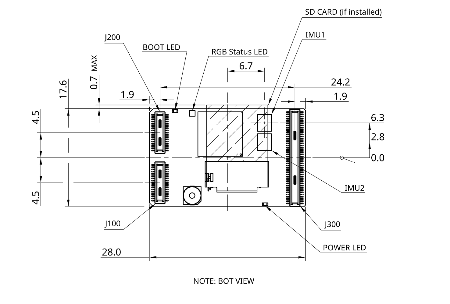
Section titled “2D drawing”A description of the board’s connectors placement is provided in the following drawing, a PDF version is available in the downloads section.
Pinout
Section titled “Pinout”Control N1 uses a new socket specification which comprises 140 pins split into 3 DF40 type connectors (Hirose). We are commited to supporting this footprint in future releases.
| Reference | Pin count | Part number | Alternative PN |
|---|---|---|---|
| J100 | 30 | DF40HC(3.5)-30DS-0.4V(51) | 10164227-0305A1RLF |
| J200 | 30 | DF40HC(3.5)-30DS-0.4V(51) | 10164227-0305A1RLF |
| J300 | 80 | DF40HC(3.5)-80DS-0.4V(51) | 10164227-0805A1RLF* |
A note on mating connector height
The 3.5mm height connector is used for the default configuration, however depending on the end user needs, a different connector height may be used. It is possible to order the board with no buzzer and no SD card slot installed, allowing for a more compact footprint.
A comprehensive pinout table is available below. The table follows the physical layout of the connectors so there are two pins per row. If you are using KiCad to capture your design, you can download the template project from our downloads section.
Pinout tool
J100
| Group | Name | Pin | Pin | Name | Group |
|---|---|---|---|---|---|
| POWER | GND | 1 | 2 | USART2_TX | SG1 |
| USB | USB_DM | 3 | 4 | USART2_RX | SG1 |
| USB | USB_DP | 5 | 6 | USART2_CTS | SG1 |
| POWER | GND | 7 | 8 | USART2_RTS | SG1 |
| SDMMC | SD_DET | 9 | 10 | GND | POWER |
| SDMMC | SDIO_D1 | 11 | 12 | UART4_TX | SG2 |
| SDMMC | SDIO_D0 | 13 | 14 | UART4_RX | SG2 |
| SDMMC | SDIO_CK | 15 | 16 | UART4_CTS | SG2 |
| POWER | GND | 17 | 18 | UART4_RTS | SG2 |
| SDMMC | SDIO_CMD | 19 | 20 | GND | POWER |
| SDMMC | SDIO_D3 | 21 | 22 | USART3_TX | SG4 |
| SDMMC | SDIO_D2 | 23 | 24 | USART3_RX | SG4 |
| POWER | GND | 25 | 26 | GND | POWER |
| MISC | ALARM | 27 | 28 | USART1_TX | SG5 |
| POWER | GND | 29 | 30 | USART1_RX | SG5 |
J200
| Group | Name | Pin | Pin | Name | Group |
|---|---|---|---|---|---|
| SWD | SWCLK | 1 | 2 | USART6_TX | SG6 |
| SWD | SWDIO | 3 | 4 | USART6_RX | SG6 |
| POWER | GND | 5 | 6 | RESERVED | - |
| - | AP_nRST | 7 | 8 | RESERVED | - |
| - | BOOT0 | 9 | 10 | GND | POWER |
| POWER | GND | 11 | 12 | RESERVED | - |
| FDCAN | FDCAN1_5V | 13 | 14 | RESERVED | - |
| FDCAN | FDCAN1_H | 15 | 16 | GND | POWER |
| FDCAN | FDCAN1_L | 17 | 18 | ADDR_LED | MISC |
| POWER | GND | 19 | 20 | RESERVED | - |
| - | BRD_EN | 21 | 22 | SPI_SCK | SPI |
| POWER | 5V_PWRIN1 | 23 | 24 | SPI_SDI | SPI |
| POWER | 5V_PWRIN1 | 25 | 26 | SPI_SDO | SPI |
| POWER | GND | 27 | 28 | SPI_nCS | SPI |
| POWER | GND | 29 | 30 | RESERVED | - |
J300
| Group | Name | Pin | Pin | Name | Group |
|---|---|---|---|---|---|
| POWER | GND | 1 | 2 | GND | POWER |
| FDCAN | FDCAN2_L | 3 | 4 | GND | POWER |
| FDCAN | FDCAN2_H | 5 | 6 | 5V_PWRIN2 | POWER |
| FDCAN | FDCAN2_5V | 7 | 8 | 5V_PWRIN2 | POWER |
| POWER | GND | 9 | 10 | 3V3_AP | POWER |
| - | RESERVED | 11 | 12 | RESERVED | - |
| - | RESERVED | 13 | 14 | RESERVED | - |
| POWER | GND | 15 | 16 | RESERVED | - |
| - | RESERVED | 17 | 18 | RESERVED | - |
| - | RESERVED | 19 | 20 | GND | POWER |
| POWER | GND | 21 | 22 | RESERVED | - |
| I2C | I2C2_SDA | 23 | 24 | RESERVED | - |
| I2C | I2C2_SCL | 25 | 26 | GND | - |
| POWER | GND | 27 | 28 | ADC1_INP10 | ADC |
| I2C | I2C1_SDA | 29 | 30 | ADC1_INP18 | ADC |
| I2C | I2C1_SCL | 31 | 32 | GND | POWER |
| POWER | GND | 33 | 34 | RESERVED | - |
| SG7 | UART8_RX | 35 | 36 | RESERVED | - |
| SG7 | UART8_TX | 37 | 38 | RESERVED | - |
| POWER | GND | 39 | 40 | RESERVED | - |
| SG3 | UART7_RTS | 41 | 42 | GND | POWER |
| SG3 | UART7_CTS | 43 | 44 | GP4 | GPIO |
| SG3 | UART7_RX | 45 | 46 | GP3 | GPIO |
| SG3 | UART7_TX | 47 | 48 | GP2 | GPIO |
| - | RESERVED | 49 | 50 | GP1 | GPIO |
| - | RESERVED | 51 | 52 | GND | POWER |
| POWER | GND | 53 | 54 | CH12 | MOT/GPIO |
| - | RESERVED | 55 | 56 | CH11 | MOT/GPIO |
| POWER | GND | 57 | 58 | CH10 | MOT/GPIO |
| - | RESERVED | 59 | 60 | CH9 | MOT/GPIO |
| - | RESERVED | 61 | 62 | GND | POWER |
| - | RESERVED | 63 | 64 | CH8 | MOT/GPIO |
| POWER | GND | 65 | 66 | CH7 | MOT/GPIO |
| - | RESERVED | 67 | 68 | CH6 | MOT/GPIO |
| POWER | GND | 69 | 70 | CH5 | MOT/GPIO |
| - | RESERVED | 71 | 72 | GND | POWER |
| - | RESERVED | 73 | 74 | CH4 | MOT/GPIO |
| POWER | GND | 75 | 76 | CH3 | MOT/GPIO |
| - | RESERVED | 77 | 78 | CH2 | MOT/GPIO |
| - | RESERVED | 79 | 80 | CH1 | MOT/GPIO |
Serial ports
Section titled “Serial ports”The serial ports are grouped into SG1, SG2, SG3, SG4, SG5, SG6, and SG7. These are arbitrary choices, but match firmware definitions. Reference documents will use these names.
| Serial group | Location | STM32 Peripheral | AP Serial param | Flow Control | Default AP function |
|---|---|---|---|---|---|
| SG1 | J100 | USART2 | SERIAL1_* | YES | TELEM1 |
| SG2 | J100 | UART4 | SERIAL2_* | YES | TELEM2 |
| SG3 | J300 | UART7 | SERIAL6_* | YES | N/A (USER) |
| SG4 | J100 | USART3 | SERIAL4_* | NO | GPS2 |
| SG5 | J100 | USART1 | SERIAL7_* | NO | N/A (USER) |
| SG6 | J200 | USART6 | SERIAL5_* | NO | ELRS RX (USER) |
| SG7 | J300 | UART8 | SERIAL3_* | NO | GPS |
What is “Default AP function”?
Ardupilot assigns a default function to the first 5 serial ports according to the following table. For more info, see Ardupilot’s wiki here.
Quick start
Section titled “Quick start”Install the board on its carrier and connect via USB to start configuring parameters and connecting peripherals.
Boards currently ship with ArduCopter-master until the stable release is available. If you wish to switch to any other firmware, visit our firmware update guide or use our new flash tool.
The bootloader provides interoperability with PX4 as well, so any ground control software should be able to detect it and load firmware adequately. There is no need to change the bootloader if you want to flash PX4.
We encourage all customers to run the latest indicated version available in the Compatibility table below for your preferred flight stack.
Supported firmware
Section titled “Supported firmware”The 3DR Control N1 is compatible with the following firmware:
ArduPilot
Section titled “ArduPilot”Some additional resources:
If you’d like to see N1 support from another flight stack let us know!
About IO coprocessors and AUX Pins
Historically, microcontrollers mounted on Autopilots didn’t have enough resources to handle the requirements that industry was demanding. Usually, the features needed to keep up with the trends, pushed manufacturers to add IO coprocessors to increase the number of available timers to generate and decode PWM signals and additional IO Pins. The coprocessor in these hardware architectures is usually connected via a single serial port, reducing the amount of data available in time and introducing points of failure. This arrangement pushed the pins to be divided by MAIN and AUX Pins, where MAIN were the pins connected to the MCU and AUX to IO coprocessors. However, later generations of hardware have increased IO pin density considerably, as well as increased the number of timers, among other enhancements. A special benefit stands out for our design principles, and it is the higher amount and more sophisticated DMAs that work really well with peripherals, transferring high amounts of data and decreasing CPU usage. Besides, DroneCAN and networking tools encourage distributed computing rather than centralized control. In practical terms, you can consider every available PWM pin in your board as you would for an AUX pin.
Available ordering options
Section titled “Available ordering options”Control N1 Product Tiers
Section titled “Control N1 Product Tiers”| Tier | Personal-Tinkerer | Industrial/Business | Partner/OEM |
|---|---|---|---|
| Support | Community | 1- or 2-day ticket response | All in Business Custom or no logo Custom sensors Custom signed BL |
| Bootloader | Open | Signed (or open) | |
| Firmware | Upstream flight stacks - PX4 and Ardupilot | Tested binaries, 3DR distributed | |
| Calibration | From IMU vendor | Factory calibrated across all temperature range after assembly Test reports Temp cycling | |
| Sensors | Standard | Upgraded | |
| Price | $99 | $149 to $549 | Contact us |
| Custom options | Description |
|---|---|
| Conformal Coating | Optional |
| Thermal calibration | Optional |
| Ultra-low profile (No SD card socket and no buzzer) | MOQ applies |
Downloads
Section titled “Downloads”2D drawing
STEP file
KiCad Carrier Board template project