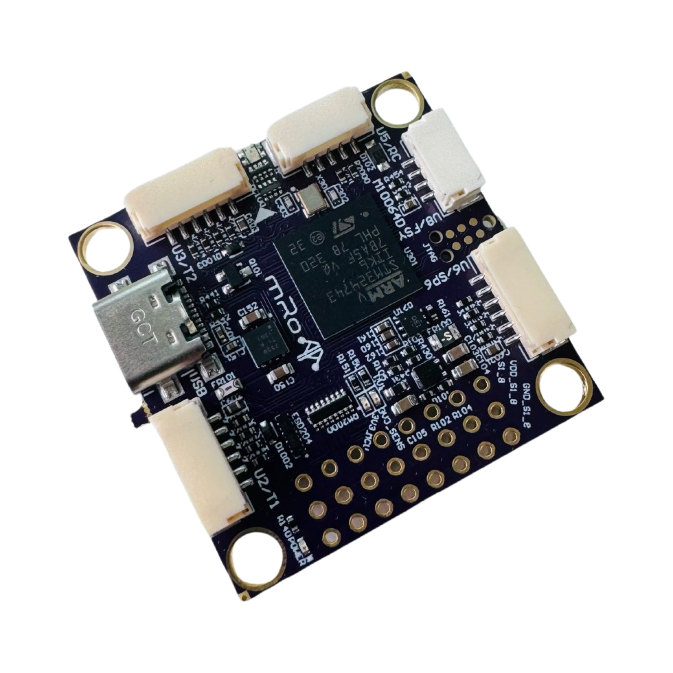
Pixracer Pro
3D View
Section titled “3D View”Description
Section titled “Description”Four years after the original Pixracer was designed and proven, we recognized the need to bring the design to the forefront of open-source flight controllers. With the Pixracer Pro, we maintained everything that the community loved about the original Pixracer (R15) and improved every known deficiencies.
Purchase Pixracer ProAbout IO coprocessors and AUX Pins
Historically, microcontrollers mounted on Autopilots didn’t have enough resources to handle the requirements that industry was demanding. Usually, the features needed to keep up with the trends, pushed manufacturers to add IO coprocessors to increase the number of available timers to generate and decode PWM signals and additional IO Pins. The coprocessor in these hardware architectures is usually connected via a single serial port, reducing the amount of data available in time and introducing more points of failure. This arrangement pushed the pins to be divided by MAIN and AUX Pins, where MAIN were the pins connected to the MCU and AUX to IO coprocessors.
However, later generations of hardware have increased IO pin density, timers and reduced size factor, among other enhancements.
Additionally, a special benefit also stands out for our design principles, and it is the higher amount and more sophisticated DMAs that work really well with peripherals, transferring high amounts of data and decreasing CPU usage. Besides, we are transitioning from a single MCU architecture to more distributed systems thanks to DroneCAN and Ethernet connectivity (coming soon). In practical terms, you can consider every available PWM pin in your board as you would for an AUX pin.
Specifications
Section titled “Specifications”| Specifications | Pixracer Pro |
|---|---|
| Main Processor | 32-bit STM32H743 Cortex M7 RISC core with FPU 460 MHz |
| IO Processor | No |
| RAM | 1024 KB RAM |
| Flash | 2 MB FRAM |
| Crypto / Hash Processor | No |
| Sensors | Bosch BMI085 (6DoF) Invensense/TDK ICM-20602 (6DOF) Invensense/TDK ICM-20948 (9DOF) |
| Internal Magnetometer | AK09916 inside ICM-20948 |
| Barometer | Infineon DPS368 barometer (Very smooth and NO light sensitivity) |
| Interfaces and Protocols | 6x UART [2x with HW flow control, 1x FRSky Telemetry (D or X types), 2x General Purpose & 1x GPS+I2C]. 1x PPM sum input signal 8x PWM outputs (all D-Shot capable) 1x RSSI (PWM or voltage) input 1x I2C 1x SPI 2x CAN 1x SWD (TC2030 Connector) 3x Ultra low-noise LDO voltage regulator Supported RC input protocols: Spektrum DSM / DSM2 / DSM-X® Satellite compatible input and binding. Futaba S.BUS® & S.BUS2® compatible input. FRSky Telemetry port output. Graupner SUMD. Yuneec ST24. |
| Connectors | JST-GH 0.1” pin headers USB-C |
| Conformal Coating | No |
| Extended Testing and Burn In | No |
| Custom Carrier Board Support | No |
| LED | Yes (RGB) |
| Dimensions | Width: 36.6mm (1.42”) Length: 36.6mm (1.42”) |
| Weight | 8.92g (.31 oz) |
| Mounting Holes | 4mm holes at 30.5mm spacing Silicone rubber grommets for M3 mounting screws |
| Protector Case | Not available |
| Typical Platforms | Multirotor Rover Fixed-Wing Boats Submarines VTOL Automatic Tractors Others |
| Compatibility | PX4 >1.13.0, Ardupilot |
Pinout
Section titled “Pinout”Top View:
Section titled “Top View:”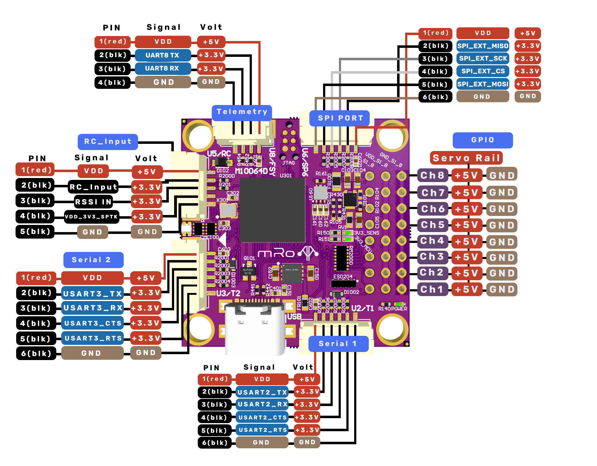
Bottom View:
Section titled “Bottom View:”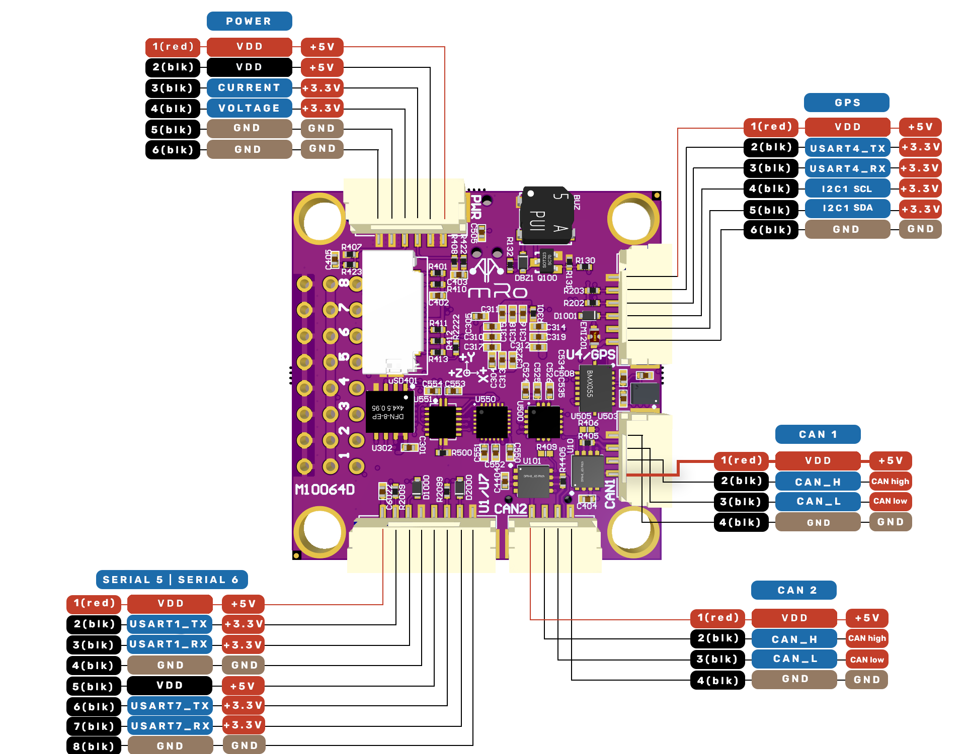
The serial ports default assignment is as follows:
| Serial | Port name | AP Serial |
|---|---|---|
| USART2 | TELEM1 | SERIAL1 |
| USART3 | TELEM2 | SERIAL2 |
| USART4 | GPS | SERIAL3 |
| USART8 | Additional UART | SERIAL4 |
| USART1 | Additional UART | SERIAL5 |
| USART7 | Additional UART | SERIAL6 |
Connector pin assignments
Section titled “Connector pin assignments”| Pin | Signal | Level/Voltage |
|---|---|---|
| 1 (red) | VDD | 5V |
| 2 (blk) | VDD | 5V |
| 3 (blk) | CURRENT | 3.3V |
| 4 (BLK) | VOLTAGE | 3.3V |
| 5 (BLK) | GND | GND |
| 6 (BLK) | GND | GND |
| Pin | Signal | Level/Voltage |
|---|---|---|
| 1 (red) | VDD | 5V |
| 2 (blk) | USART4_TX | 3.3V |
| 3 (blk) | USART4_RX | 3.3V |
| 4 (blk) | I2C_SCL | 3.3V |
| 5 (blk) | I2C_SDA | 3.3V |
| 6 (blk) | GND | GND |
TELEMETRY
Section titled “TELEMETRY”| Pin | Signal | Level/Voltage |
|---|---|---|
| 1 (red) | VDD | 5V |
| 2 (blk) | UART8_TX | 3.3V |
| 3 (blk) | UART8_RX | 3.3V |
| 4 (blk) | GND | GND |
SPI PORT
Section titled “SPI PORT”| Pin | Signal | Level/Voltage |
|---|---|---|
| 1 (red) | VDD | 5V |
| 2 (blk) | SPI_EXT_MISO | 3.3V |
| 3 (blk) | SPI_EXT_SCK | 3.3V |
| 4 (blk) | SPI_EXT_CS | 3.3V |
| 5 (blk) | SPI_EXT_MOSI | 3.3V |
| 6 (blk) | GND | GND |
CAN 1 & CAN 2
Section titled “CAN 1 & CAN 2”| Pin | Signal | Level/Voltage |
|---|---|---|
| 1 (red) | VDD | 5V |
| 2 (blk) | CAN_H | CAN high |
| 3 (blk) | CAN_L | CAN low |
| 4 (blk) | GND | GND |
SERIAL 1
Section titled “SERIAL 1”| Pin | Signal | Level/Voltage |
|---|---|---|
| 1 (red) | VDD | 5V |
| 2 (blk) | USART2_TX | 3.3V |
| 3 (blk) | USART2_RX | 3.3V |
| 4 (blk) | USART2_CTS | 3.3V |
| 5 (blk) | USART2_RTS | 3.3V |
| 6 (blk) | GND | GND |
SERIAL 2
Section titled “SERIAL 2”| Pin | Signal | Level/Voltage |
|---|---|---|
| 1 (red) | VDD | 5V |
| 2 (blk) | USART3_TX | 3.3V |
| 3 (blk) | USART3_RX | 3.3V |
| 4 (blk) | USART3_CTS | 3.3V |
| 5 (blk) | USART3_RTS | 3.3V |
| 6 (blk) | GND | GND |
SERIAL 5 & SERIAL 6
Section titled “SERIAL 5 & SERIAL 6”| Pin | Signal | Voltage |
|---|---|---|
| 1 (red) | VDD | 5V |
| 2 (blk) | USART1_TX | 3V3 |
| 3 (blk) | USART1_RX | 3V3 |
| 4 (blk) | GND | GND |
| 5 (blk) | VDD | 5V |
| 6 (blk) | USART7_TX | 3V3 |
| 7 (blk) | USART7_RX | 3V3 |
| 8 (blk) | GND | GND |
RC_Input
Section titled “RC_Input”| Pin | Signal | Voltage |
|---|---|---|
| 1 (red) | VDD | 5V |
| 2 (blk) | RC_Input | 3.3V |
| 3 (blk) | RSSI IN | 3.3V |
| 4 (blk) | VDD_3V3_SPKT | 3.3V |
| 5 (blk) | GND | GND |
GPIO (USB port side up / SD card slot down)
Section titled “GPIO (USB port side up / SD card slot down)”| LEFT | Middle (servo rail) | Right |
|---|---|---|
| CH 8 | +5V | GND |
| CH 7 | +5V | GND |
| CH 6 | +5V | GND |
| CH 5 | +5V | GND |
| CH 4 | +5V | GND |
| CH 3 | +5V | GND |
| CH 2 | +5V | GND |
| CH 1 | +5V | GND |
Firmware
Section titled “Firmware”The 3DR Pixracer Pro is compatible with the following firmware:
ArduPilot
Section titled “ArduPilot”Compatible with all vehicle types.
- PX4 stable greater than v1.13.3

Usage Guide
Section titled “Usage Guide”BATT_VOLT_PIN= 14BATT_CURR_PIN= 15
All connectors follow the Dronecode connector standard. All connectors are JST-GH.
Pixracer Pro does not have a safety switch option. If there’s a need to have one, a CAN switch is required.
What’s included
Section titled “What’s included”- 1x SD Card
- 1x Right angle 3×8 0.1″ header pin
- 1x Connector GH Housing 8 position 1.25 mm
- 2x Connector GH Housing 6 position 1.25 mm
- 4x Rubber Balls (Dampers)
- 1x Heatsink
- 2x MRC0206 3DR 6-Pins JST-GH to 6-Pins JST-GH
- 1x MRC0202 3DR 6-Pins JST-GH to 6 Separate 2.54mm Females
- 1x MRC0204 3DR 5-Pins JST-GH to 3-Pins Servo and 3-Pins JST-ZHR and 1-Pin (2.54mm) Female
- 1x MRC0205 3DR 4-Pins JST-GH to 4-Pins JST-GH
- 1x MRC0287 3DR 8-Pin JST-GH to 8PCS Dupont 1Pin Connector
- 1x MRC0288 3DR 8-Pin JST-GH to 2PCS JST-GH 4Pin Connector
Extra Features
Section titled “Extra Features”Pixracer Pro has a built-in buzzer.