CAN Node F303 - M10042 
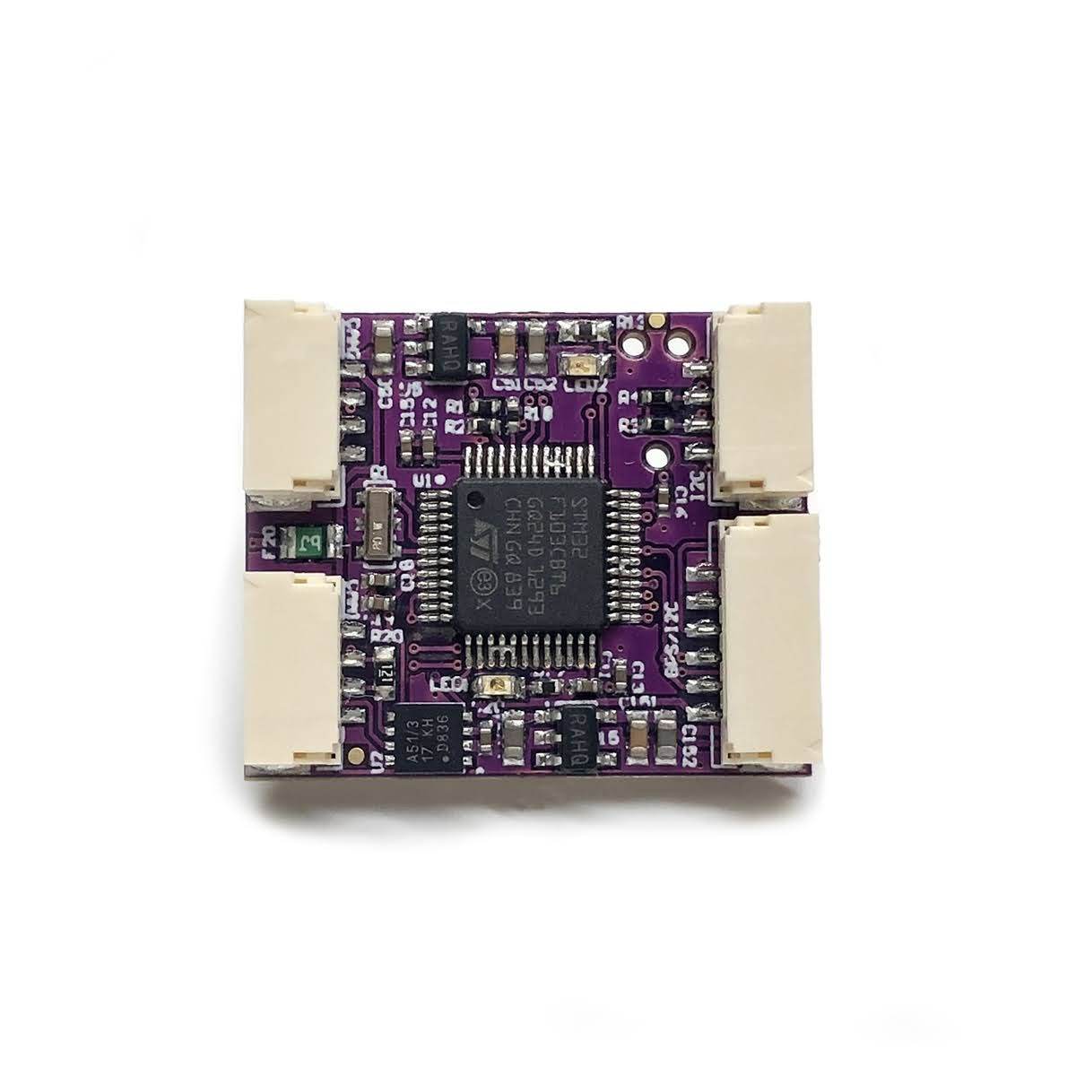
The CAN Node is a product of a collaborative effort with Ardupilot, stemming from a shared ambition to establish CAN peripherals as a standard in the drone community. Unlike other boards with open-source hardware but closed-source code, the CAN Node is fully open. The CAN Node F303 represents the second iteration of our CAN Node, offering increased flash space.
| Specification | Value |
|---|---|
| Microcontroller | STM32F303 ARM Microcontroller |
| Dimensions | 25 mm x 21 mm |
| Weight | 3.20 g |
| UART | 2 (GPS Port and solder pads) |
| CAN | 1 (shared) |
| I2C | 1 (GPS port and solder pads) |
| SPI | 1 (2 Chip Selects) |
| ADC | 2 lines |
| GPIO | 3 lines |
| Operating voltage | 5 V |
| Max. Current | 500 mA |
| Firmware | AP_Periph: f303-Universal |
![]()
Featuring AP_Periph firmware, the CAN Node includes a CAN bootloader for effortless updates through the same CAN port. Users can configure onboard parameters with specific CAN Node IDs or opt for auto-allocated IDs. The hardware design is free and open-source, enabling contributions to the CAN peripheral domain using a proven CAN/MCU interface.
Setup
Quick Start
Make sure you are using the latest version of Mission Planner. With the following firmware versions or newer:
| Parameter | Value |
|---|---|
| ArduPlane | v4.0.5 |
| ArduCopter | v4.0.3 |
| ArduRover | v4.0.0 |
Go to Full Parameter Tree on Mission Planner and verify the following are enabled:
| Parameter | Value |
|---|---|
| CAN_P1_DRIVER | 1 |
| GPS_TYPE | 9 UAVCAN |
Make sure the UAVCAN compass driver is not disabled (UAVCAN should be unchecked).
If your controller has more than 3 internal compasses, you should disable the least important one:
| Parameter | Value |
|---|---|
| COMPASS_TYPEMASK | UAVCAN (Unchecked) |
I2C Airspeed sensor
If you want to enable the I2C airspeed, on the autopilot/controller parameters via Mission Planner set ARSPD_TYPE = 8 UAVCAN
Use the following parameters depending on the type of airspeed you are connecting.
ARSPD_TYPE = 1For I2C Airspeed Sensor JST-GH MS4525DOARSPD_TYPE = 4For MS5525
Port pinout tables
GPS Port
| Pin | Color | Signal | TTL/Voltage Level |
|---|---|---|---|
| 1 | red | VCC | 5V |
| 2 | black | TX | 3V3 |
| 3 | black | RX | 3V3 |
| 4 | black | I2C_SCL | 3V3 |
| 5 | black | I2C_SDA | 3V3 |
| 6 | black | GND | GND |
CAN Port
| Pin | Color | Signal | TTL/Voltage Level |
|---|---|---|---|
| 1 | red | VCC | 5V |
| 2 | black | CAN_H | |
| 3 | black | CAN_L | |
| 4 | black | GND | GND |
I²C Port
| Pin | Color | Signal | TTL/Voltage Level |
|---|---|---|---|
| 1 | red | VCC | 5V |
| 2 | black | I2C_SCL (pull-up on autopilot) | 3V3 |
| 3 | black | I2C_SDA (pull-up on autopilot) | 3V3 |
| 4 | black | GND | GND |