NewRev A.0
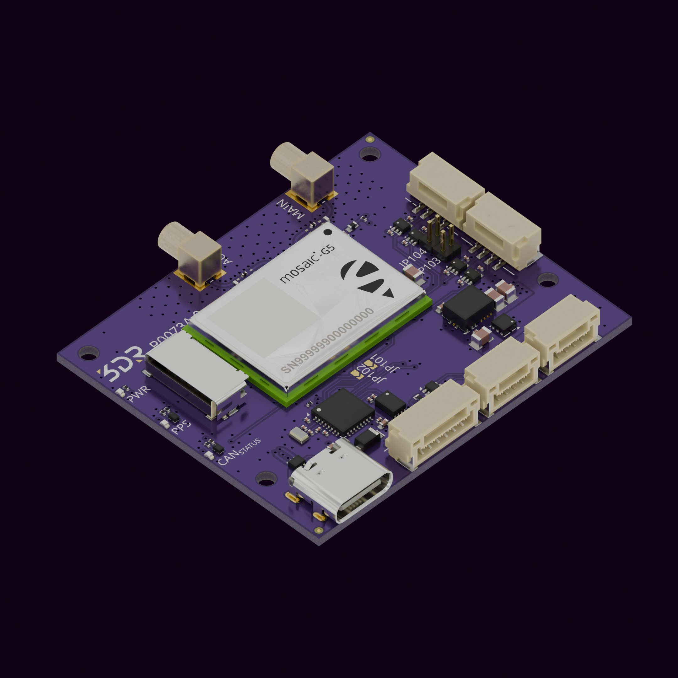
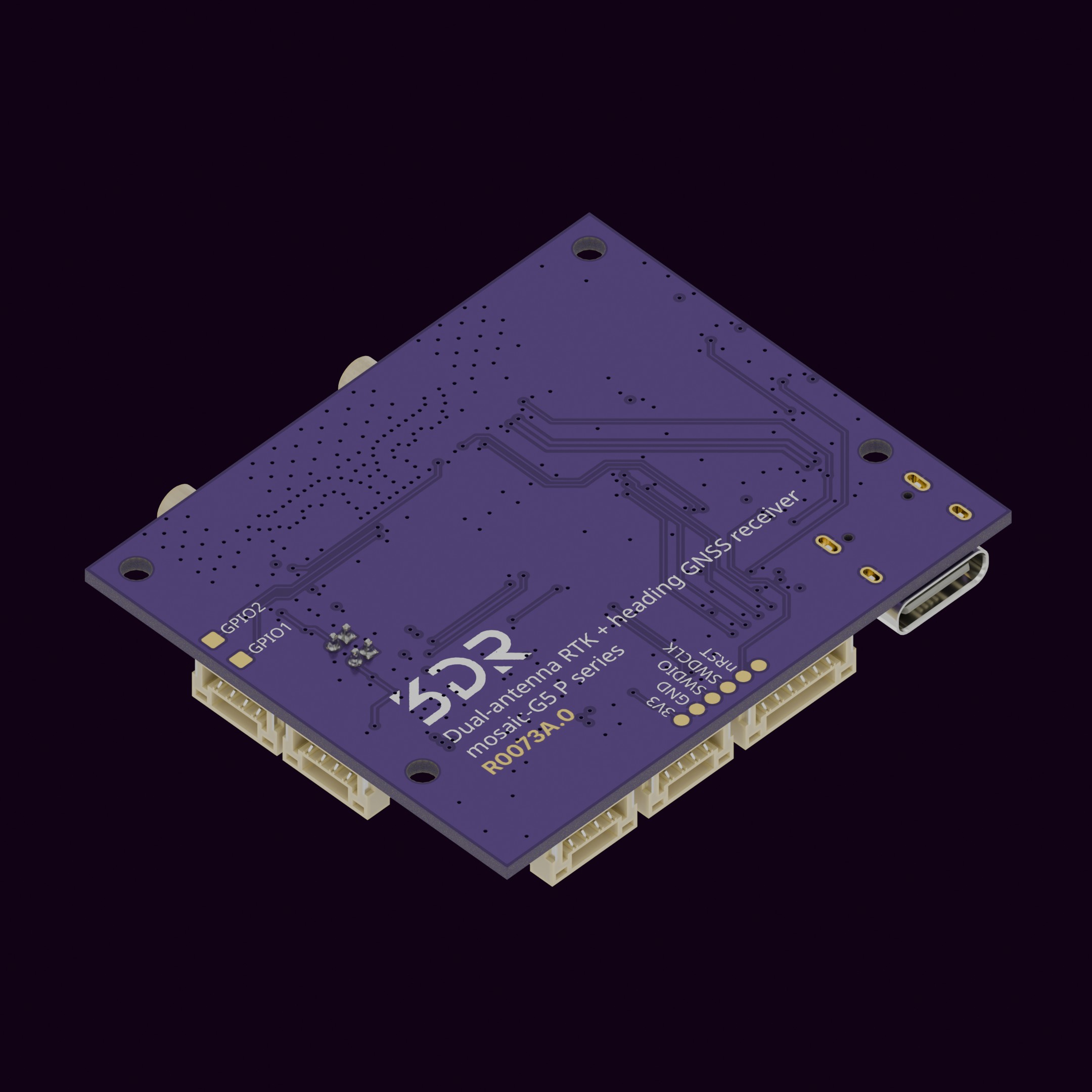
The 3DR mosaic-G5 P3H Heading GNSS (R0073) brings Septentrio’s newest receiver to the DroneCAN ecosystem. The mosaic-G5 P3H is a quad-band, all-constellation RTK receiver with dual antenna inputs, so a single board delivers centimeter-level position and GNSS heading with no dependence on a magnetometer. It is ideal for fixed-wing, VTOL, marine and ground platforms where compass interference or low dynamics make magnetic heading unreliable.
We added our L4 CAN Periph node, bridging mosaic-G5’s COM1 port to DroneCAN. The receiver’s second UART, both PPS outputs, both event inputs, USB-C and a microSD logging slot are all broken out on standard JST-GH and USB-C connectors, so the board works equally well as a DroneCAN GNSS, as a serial GNSS, or as a standalone RTK base/rover and data logger.
This board supports 5–36 V input on a GH type connector (2S–8S direct from the battery).
Purchase now| Feature | 3DR mosaic-G5 P3H Heading GNSS |
|---|
| GNSS receiver | Septentrio mosaic-G5 P3H: GPS, GLONASS, Galileo, BeiDou, QZSS, SBAS. Quad-band (single antenna) / triple-band (dual antenna) |
| Heading | Dual-antenna GNSS heading + pitch or roll. Sub-degree accuracy, no magnetometer required |
| RTK / PPP | RTK rover and base (RTCM), Galileo HAS, Septentrio AIM+ anti-jamming and anti-spoofing, LOCK+ high-vibration tracking, RAIM+ |
| Communication | DroneCAN via AP_Periph on STM32L431 (Cortex-M4, 80 MHz) with ATA6501 CAN-FD transceiver |
| Serial | GNSS COM2 with RTS/CTS on 6-pin JST-GH (Pixhawk standard). COM1 internally routed to the CAN node |
| Timing | Two PPS outputs and two event inputs on dedicated 4-pin JST-GH timing ports, level-translated to the host’s I/O voltage (1.65–5.5 V). xPPS precision 1.4 ns, event timestamp < 3 ns |
| USB-C | Direct high-speed USB (480 Mbps) to the receiver for RxTools, firmware update and configuration. Also powers the board |
| Logging | Onboard push-pull microSD slot for internal receiver logging |
| Antenna ports | 2 × MMCX (MAIN / AUX), 3.3 V antenna bias, TVS + series protection |
| Input protection | 5–36 V input with TVS3300 flat-clamp surge protection, Schottky-ORed battery and USB inputs, ESD protection on USB, CAN and antenna ports |
| Status LEDs | Power, PPS (GNSS fix), CAN node status |
| Specifications | 3DR mosaic-G5 P3H Heading GNSS |
|---|
| GNSS module | Septentrio mosaic-G5 P3H |
| Constellations | GPS, GLONASS, Galileo, BeiDou, QZSS, SBAS |
| Position accuracy (RTK) | 0.6 cm + 0.5 ppm horizontal, 1 cm + 1 ppm vertical |
| Position accuracy (standalone / DGNSS) | 1.2 m / 0.4 m horizontal |
| Heading accuracy | 0.15° at 1 m baseline (per Septentrio) |
| Update rate | Up to 100 Hz |
| RTK initialization / cold start | 7 s / < 35 s |
| CAN | 1 × CAN-FD, JST-GH 4-pin, DroneCAN |
| Serial | 1 × UART with RTS/CTS (GNSS COM2), JST-GH 6-pin |
| Storage | microSD (push-pull) |
| Input voltage | 5–36 V (JST-GH 4-pin) or 5 V via USB-C |
| RTK ready | Yes (rover and base) |
| USB Port | Yes (Type C) |
| SD logging | Yes |
| Minimum and Maximum Operating Temperature | -40 ~ 85 °C (module rating) |
| LED | PWR, PPS, CAN Status |
| Dimensions | 49 × 41 mm |
| Mounting Holes | 4 × Ø2.2 mm for M2 screws |
| Firmware | ArduPilot AP_Periph (DroneCAN). Receiver configured via Septentrio RxTools |
| Port | Connector | Function |
|---|
| PWR | JST-GH 4-pin | 5–36 V battery input |
| USB | USB-C | Receiver USB, board power |
| CAN | JST-GH 4-pin | DroneCAN (CAN-FD capable) |
| SERIAL2 | JST-GH 6-pin | GNSS COM2, UART with RTS/CTS, Pixhawk pinout |
| TIMING A | JST-GH 4-pin | PPS1 out, Event A in, VIOA reference |
| TIMING B | JST-GH 4-pin | PPS2 out, Event B in, VIOB reference |
| ANT1 (MAIN) / ANT2 (AUX) | MMCX | Main / auxiliary antenna, 3.3 V bias |
| microSD | Push-pull socket | Receiver logging |
All ports are JST-GH connectors, with pin 1 being the left when holding the cable tab up.
| Pin | Signal | TTL/Voltage Level |
|---|
| 1 | VCC | 5–36 V |
| 2 | VCC | 5–36 V |
| 3 | GND | N/A |
| 4 | GND | N/A |
| Pin | Signal | TTL/Voltage Level |
|---|
| 1 | VDD | 5-36 V |
| 2 | CAN_H | N/A |
| 3 | CAN_L | N/A |
| 4 | GND | N/A |
| Pin | Signal | TTL/Voltage Level |
|---|
| 1 | VDD | 5-36 V |
| 2 | RX2 (into receiver) | 3V3 |
| 3 | TX2 (out of receiver) | 3V3 |
| 4 | RTS2 | 3V3 |
| 5 | CTS2 | 3V3 |
| 6 | GND | N/A |
| Pin | Signal | TTL/Voltage Level |
|---|
| 1 | VIOA / VIOB (I/O voltage reference input) | 1.65–5.5 V, see JP103 / JP104 |
| 2 | PPS1 / PPS2 output | VIO |
| 3 | EVENT A / EVENT B input | VIO |
| 4 | GND | N/A |
The PPS and event signals are level-translated: each port carries its own I/O-voltage reference pin, so PPS and event signals can interface directly with 1.8 V, 3.3 V or 5 V hosts. If the host does not supply VIO, the port’s signals are inactive until JP103 (port A) or JP104 (port B) is closed to tie VIO to the board’s 3.3 V rail.
mosaic-G5 USB port (USB 2.0 High Speed), also powers the board at 5 V.
| Jumper | Type | Function |
|---|
| JP101 | Solder jumper | Routes Event A to the CAN node interrupt input (INT0) |
| JP102 | Solder jumper | Routes PPS1 to the CAN node interrupt input (INT1) |
| JP103 | 1.27 mm 2-pin header | Ties VIOA (TIMING A pin 1) to board 3.3 V |
| JP104 | 1.27 mm 2-pin header | Ties VIOB (TIMING B pin 1) to board 3.3 V |
| LED | Position | Meaning |
|---|
| PWR | Left edge, top | 3.3 V rail present |
| PPS | Left edge, middle | Follows the receiver’s PPS1 output. Blinks once per second once the receiver has a fix |
| CAN | Left edge, bottom | CAN node status (AP_Periph) |
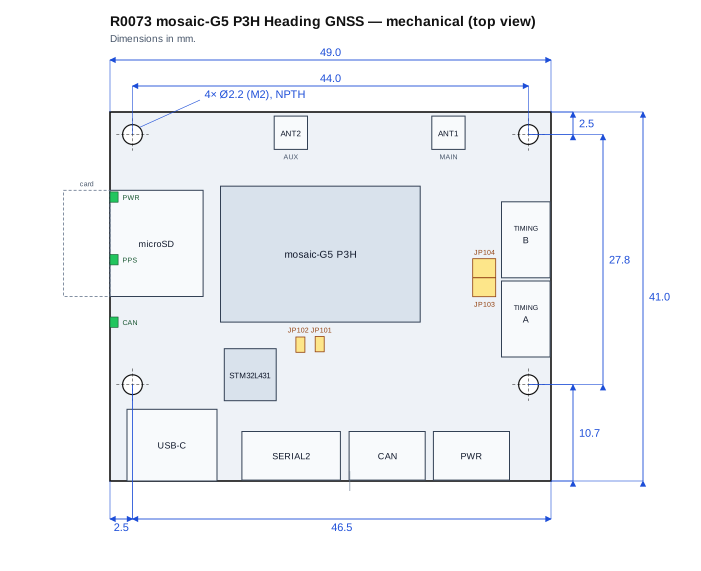
| Mechanical specs | Value |
|---|
| Board outline | 49.0 × 41.0 mm |
| PCB thickness | 1.2 mm |
| Mounting holes | 4 × Ø2.2 mm for M2 screws |
| Hole pattern | 44.0 × 27.8 mm |
Mounting hole coordinates (origin at the bottom-left corner, top view, X to the right, Y up)
| Hole | X (mm) | Y (mm) |
|---|
| Top-left | 2.5 | 38.5 |
| Top-right | 46.5 | 38.5 |
| Bottom-left | 2.5 | 10.7 |
| Bottom-right | 46.5 | 10.7 |
- 1 × 3DR mosaic-G5 P3H Heading GNSS board (R0073)
- 1 × MRC0205, 4-pin JST-GH to 4-pin JST-GH CAN cable (150 mm)
- 1 × MRC0206, 6-pin JST-GH to 6-pin JST-GH cable (150 mm)
Please contact us if you have any questions or need further assistance.